Class Diagram to Ralational Database Definition (recursive)
Ā
The example is taken literally as specified in the workshop call for papers (CFP).
However, the lately added to FAQ comment that subclasses of persistent classes do not
add new elements to the primary key is not used - we permit primary attributes to be
merged up to the persistent class. All diagrams of the proposed MOLA solution are shown
in Fig. 1 - 11.
Metamodel of the example
ĀĀ
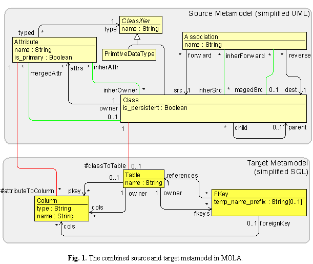
Fig. 1 shows the metamodel of the example. In MOLA source and target metamodels (if different)
must be combined in one class diagram. The upper region in Fig. 1 is the source metamodel
(simplified UML) and the lower one is the target (simplified SQL). The regions are just
graphical comments. All black associations are the original ones.
ĀĀ
MOLA uses a slightly simplified EMOF syntax for metamodels. Association multiplicities must
be explicit in MOLA, therefore the default ones have been added. Some role names for
non-navigable ends also have been added (they are not mandatory for transformations,
but ease the instance management in MOLA environment).
ĀĀ
Associations in colors other than black have a special meaning in MOLA.
The green ones are temporary - they are not present in the source model, but built
by MOLA programs to store some intermediate relations. They are not also included in
the resulting model. The red ones are the mapping associations, typically they link
classes in source metamodel to target ones. They are built by MOLA programs, and their
role is similar to relations, e.g., in QVT-Merge language - to transfer the results of
high level transformations to subordinated ones and to facilitate the definition of
inverse transformations (they are retained in the resulting model).
ĀĀ
Fig. 1 contains two intermediate relations between Class and Attribute and between Class
and Association - they are used to relate all (transitively) inherited elements
(according to the standard UML semantics) and all "transitively merged-up" elements -
as specified by the example requirements. See next chapters, how their use
makes the transformations more readable. There are also two mapping associations - from
Class to Table and from Attribute to Column. They serve as a "backbone" for defining the
correspondence between the source and target models, e.g., it is very convenient to find
easy, whether a table for a class has been built and namely which. A temporary attribute
temp_name_prefix is also added to Fkey class (certainly, with multiplicity 0..1) - to
store a temporary string. Actually, the role of all these additional metamodel elements
is clearly visible when transformations themselves are discussed, and normally they
are added "on the fly" during the transformation program design.
The main program of transformation
ĀĀ
Now the transformation itself as a set of MOLA programs is being described. We start
with the description of the main program, where the main principles of the proposed
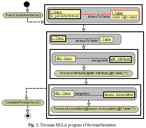
solution can be seen. Fig. 2 shows the main MOLA program.
ĀĀ
We start with some comments on the transformation algorithm. Inheritance-related items
6 and 7 of the requirements specification, together with the specified precondition on
inheritance (persistent classes are topmost parents), suggest that it would be convenient
to process transitively the inheritance as the first step. More precisely, for non-persistent
classes the traditional UML inheritance semantics must be applied, while for persistent
classes the "transitive merge up" semantics must be used. The results of this transitive
closure for a non-persistent class can be stored by means of temporary associations
inherAttr (to all inherited attributes - including the direct ones) or inherSrc
(to exiting associations), and mergedAttr/mergedSrc for persistent classes respectively.
Namely this inheritance processing is performed in the subprogram TransCloseInheritance.
In all the follow-up activities the appropriate temporary associations are used instead of
the original ones (attrs or src). It should be noted that many "classical" UML tools
(including Rose by IBM Rational) process the inheritance namely this way - you can
always see all inherited attributes/associations of a class directly.
ĀĀ
Now the comments on the MOLA program are given. We remind that MOLA control flows have
some similarity to UML activity diagram - the same Start/End symbols are used.
After the subprogram call for inheritance processing, the first FOREACH loop starts.
This loop builds an equally named table for each persistent class - note the simple
pattern consisting only of the loop variable (c:Class) itself (with the attribute
constraint expressing the persistence). An assignment expression in MOLA can contain
attributes from all elements in the same loop head (or rule), prefixed by the element name.
In addition to the Table instance, an instance of the mapping association is also built.
The next loop actually again iterates over all persistent classes, but it has a different
pattern - formally, loop over all Class instances which have a link to a Table instance
(which is the same since such a link and instance have been built in the previous loop).
The reason why we use the other pattern now is that we want to reference both the class
(@c:Class) and its table (@t:Table) in the loop body. And in turn, we couldn't insert
all the actions in this loop body into the first loop - we want to build also foreign
keys (in the nested subprograms), which reference another table, and during the first
loop it could happen that the target table is not yet built.
ĀĀ
The body of this loop does the main job in the whole transformation. At the top level,
it consists of two nested loops - for each merged up Attribute (i.e., having the
temporary mergedAttr link to the current Class instance) invoke the ProcessAttribute
subprogram with appropriate parameters and for each merged up exiting Association invoke
the ProcessAssociation. Namely, the use of mergedAttr and mergedSrc links (built by
the TransCloseInheritance subprogram) ensures the fulfilment of item 7 in the requirements
specification - "the resultant table should contain the merged columns from all of
its subclasses". The subprograms ProcessAttribute and ProcessAssociation are recursive -
they invoke themselves (indirectly), thus implementing the recursive definition of names
for target columns (and the recursive drill-down as such). The third (string) parameter
of these subprograms is the currently cumulated up name prefix - for the top level
invocation it is just empty string. The second parameter is the Table instance to
which the generated Column (if any) or FKey must be attached. These subprograms actually
implement rules 2, 3, 4, 5 of the requirements specification.
ĀĀ
When the main job is done, there still remains something to do - foreign keys have no columns.
The reason, why we couldn't fill them up "on the fly" again is - an FK must have columns
corresponding to all columns of the referenced PK, and that PK could yet be undefined.
So a separate subprogram CompleteForeignKeys completes the job.
The principal subprograms of the transformation
ĀĀ
In this section we analyze the principal subprograms of the transformation:
ProcessAttribute, ProcessAssociation, BuildColumn, BuildForeignKey and ProcessNonPersistent,
which jointly perform the recursive drill-down of attributes and associations for a class.
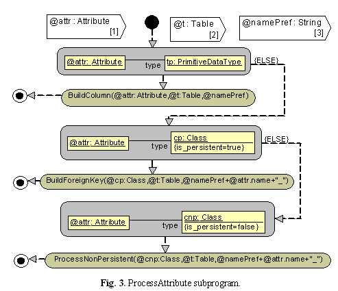
We start with the ProcessAttribute (Fig. 3). It has three parameters - the attribute to
be processed, the table to which to add the result and the cumulated name prefix (string).
ĀĀ
This relatively straightforward subprogram implements items 3, 4 and 5 of the specification,
by invoking the relevant subprograms. It contains no loops, but only rules.
The first rule acts as a precondition for the item 3 - "an attribute has a primitive data type",
therefore its unmarked (positive) exit leads to BuildColumn with appropriate parameters.
If the pattern fails (the attribute's type is not primitive) the ELSE exit is taken.
Similar graphical if-then-else constructs implement the other two cases (build foreign
key if the type is a persistent class, invoke recursive processing of a
non-persistent class). In both these cases the name prefix is prolonged - current
attribute name added to it.
ĀĀ
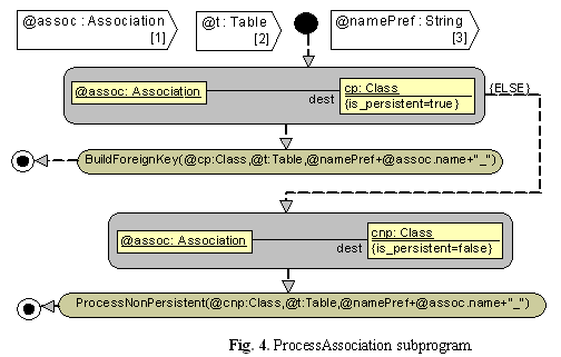
The ProcessAssociation subprogram (Fig. 4) is quite similar, except that only two cases
are possible (there is no direct column generation from an association).
ĀĀ
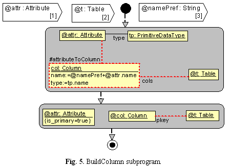
The BuildColumn (Fig. 5) subprogram is also quite simple, it contains only rules for building
instances (the ELSE exit of the first rule is semantically impossible; if the pattern
does not match for the second rule the default program end is used).
ĀĀ
In addition to building a column (using both the prefix and the current attribute), a primary
attribute enforces the column to be included into the PK list.
Similarly, the BuildForeignKey subprogram (Fig. 6) contains a rule for building a foreign key,
together with its reference to the target (note that the required dt:Table instance now exists
for sure).

ĀĀ
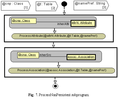
The final subprogram in this set is ProcessNonPersistent (Fig.7), which completes the recursion
(item 2 in the requirements) for a non-persistent class (by processing all its inherited
attributes and exiting associations).
Other subprograms of the transformation
ĀĀ
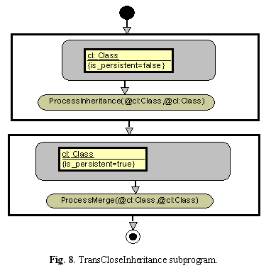
We start with the TransCloseInheritance subprogram (Fig. 8), which was already mentioned in
4.2. Its role is extremely simple - for non-persistent classes perform ProcessInheritance,
but for persistent - ProcessMerge (it was already explained in previous chapter, why the specification
implies such division). Both these subprograms process parent links recursively, therefore
the "initial calls" to them have both parameters set to reference the current class
(a class attribute is also an inherited attribute and so on). Alternatively, there
could be one loop iterating over all classes, but with an if-then-else in the body.
ĀĀ
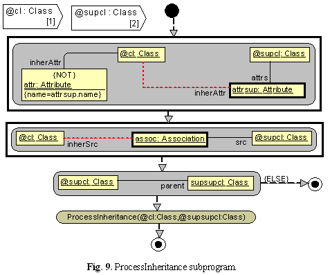
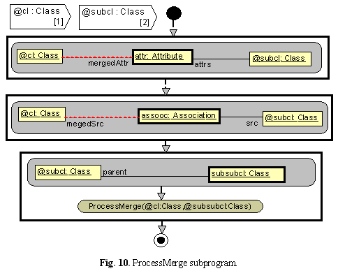
Subprograms performing the real transitive closure - ProcessInheritance (Fig. 9) and
ProcessMerge (Fig. 10) are very similar - the former iterates up via parent link,
the latter - down. However, the difference in closure semantics implies some difference
in programs. For inheritance, an attribute must not be inherited if there already is an
(inherited) attribute with the same name. This fact is expressed by (the only one in the
whole example) NOT constraint in the attr:Atribute pattern element - the instance of attrsup:Attribute doesn't match, if there is an instance of Attribute linked via inherAttr to the same Class and having a name equal to attrsup name.
ĀĀ
Since the "up" multiplicity of parent is 0..1, there is no loop involving the recursive call, but just an if-then-else branch.
ĀĀ
The ProcesMerge subprogram is simpler - there is no overriding in the merge definition. On the other hand, the "down" multiplicity of the parent link is *, therefore the recursive call is within a loop.
ĀĀ
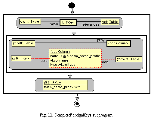
Finally, the CompleteForeignKeys subprogram does a simple job - it runs through all foreign keys and for each builds a set of columns (one for each column of the relevant primary key), using the name prefix, temporarily stored in FKey by the BuildForeignKey subprogram. Then the temporary attribute is cleared.
Use of MOLA TEE for the example
When a transformation is defined in MOLA (using the MOLA TDE) it can be compiled to check its syntax. However, a proper transformation validation can be done only using source model test examples within the MOLA TEE. Only the GMF-based version can be used for the example, since its metamodel is not part of the standard UML. Some visual facilities for building source models and viewing the transformed target models must be defined in GMF.
Initially the MOLA metamodel (combined) must be ported into the GMF metamodeling facility. In the case of the simple metamodel for the example (Fig.1) this could be done without any complexities (namely to facilitate the porting some role names were already added to the metamodel).
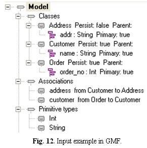
At first the simplest way of instance visualization - via customized model trees will be demonstrated. This approach is similar to the generated from a (meta) model tree and editor set in Eclipse EMF, but is significantly more flexible. For example, we can chose to represent a Class instance as a node, which shows the name, persistence and possible parent (the latter ones with keyword style separators to distinguish, which of the values are present). Then we can specify that child nodes of this node correspond to Attribute instances of the class (i.e., accessible via attrs link), each node showing the name, type and "primarity". Additional node type can be defined for associations, containing name plus source and target class names. Primitive types also must be shown as nodes. In addition, customized object dialogs can be defined for the main metaclasses (here Class and Association, with attributes as elements inside the Class dialog). GMF has also default object dialogs (like property editors in EMF), but they can be not so convenient for use. Fig. 12 shows the example tree in GMF (according to the abovementioned definitions), which corresponds to the input example - Fig. 2 from the workshop CFP. Parent is empty everywhere since there is no inheritance in this example (there is no way to remove the separator if the value is empty).
Similarly, tree nodes for the target model must be defined. Here the sole top level node should be Table, showing the name. It has two types of children - columns and foreign keys. Column nodes display name, type and whether part of PK. For both table and column nodes it can be shown from which source model elements they were generated (via the mapping associations), visually separated by ":<-" string - this is an element of explicit traceability. For foreign key nodes the referenced table may be shown, with included columns as children nodes.
Now it remains to export the instance data (source model) from GMF repository to MOLA runtime repository, start the selected transformation and import back the transformed model to the GMF repository. All these actions have been added as standard services to GMF. Fig. 13 shows what was obtained from the source model in Fig. 12.
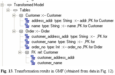 It can be easily verified, that the results do comply with the Fig. 4 in the CFP (columns which are not PK show the empty ",PK for " separator, columns which are not direct maps of source model attributes, show empty ":<-" string). Namely this way the sole transformation error was detected - the underscore symbol in names initially was placed wrongly.
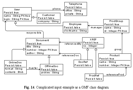
Certainly, to validate the defined transformation to a certain degree, much more test examples would be needed, e.g., inheritance is not tested at all. Larger examples can be built via this visualization for sure, but we want to demonstrate briefly the other possibility in GMF - present models as custom diagrams. Both the source and target metamodels of the example satisfy "GMF diagramming" requirements, only a special metaclass (representing a "domain diagram") must be added to each. This requires also one "technical subprogram" to be added to the transformation end - the domain diagram instance must also be built automatically. All these "scaffolding activities" in no way affect the original models or transformation. Fig. 14 shows the source model represented as a slightly non-standard class diagram - according to the assumed metamodel. Additional metaattributes (is_persistent, is_primary) are displayed as tagged values. Definition of this diagram-style presentation is more complicated, it must be specified, e.g., that Class maps to an auxiliary metamodel element ClassSymbol, which in turn has a rectangular shape and contains three text compartments one of which (for attributes) is a list compartment. Thus a sort of model transformation (domain to presentation) actually is defined in GMF, more details can be found in this publication. The definition result is a "normal" graphical editor for this variation of class diagrams, with standard facilities to be found in diagramming tools. The example in Fig. 14 (built via this editor) is a slightly adapted advanced case study (Fig. 5 in CFP), which was not meant to be used for the strict transformation rules of the mandatory example (therefore the results will be slightly unexpected). The adaptation had to be done to satisfy the preconditions on class models. Nevertheless it is a good test for the transformation - many "use cases" can be observed on it.
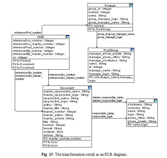
Transformation results frequently also can be displayed as a diagram, in this case an "RDBdiagram" (somewhat similar to Fig. 6 in CFP ) is defined. Tables are presented as rectangles showing columns in a list compartment, separate compartments present members of PK and the reference for each of the FKs. The columns included in an FK are shown as a list attached to the line representing this FK (unfortunately, FKs have no names in this transformation). When the transformation is run on the example and the transformed instances imported back into GMF, the diagram itself is displayed automatically via the GMF auto-layout facility.
Fig. 15 shows the result of transformation when applied to the model in Fig. 14. It can be noted that only persistent classes result into tables, but inheritance and drill-down generate a lot of new columns - according to the transformation specification. No transformation program errors were detected in this test, which can be considered as an exhaustive enough (though authors have not tried to apply any formal testing completeness criteria). The only conclusion is that in practice more sophisticated transformations from class models to RDB should be used.