UML Statechart to Simple Statechart
This is another popular example for model
transformations – the flattening of a UML statechart. UML statechart, in
addition to simple states (those used in the mathematical concept of FSM)
contains also composite states of two kinds – sequential or OR-states
(containing just one region) and concurrent or AND-states (containing more than
one region). A similar example was first used in [1] to demonstrate the GReAT
transformation language. We use here a version where the statechart can contain
only sequential composite states (OR-states in terms of [1]). Therefore the
metamodel does not contain the Region concept at all. Composite states may
contain any type of states – composite, simple, initial or final, with an
arbitrary nesting level. Such a statechart must be transformed into an
equivalent “flat” statechart (which contains only simple states). The informal
flattening algorithm is well known (most probably, formulated by D. Harel [2]).
The simplified
metamodel of the “full” (hierarchical) statechart is depicted in Fig. 1. There
are some constraints to the metamodel specifying what is a valid statechart.
There are “normal” transitions for which the event name is nonempty and
“special” ones with empty event. These empty transitions have a special role
for state structuring. Each composite state must contain exactly one initial
state (an instance of Init) and may have several final states. There
must be exactly one empty transition from the initial state of a composite
state (leading to the “default” internal state). The same way, there must be
exactly one empty transition from the composite state itself - the default exit. This exit is used when a
contained final state is reached. Otherwise, transitions may freely cross composite
state boundaries and all other transitions must be named. Named transitions
from a composite state have a special meaning (the “interrupting” events), they
actually mean an equally named transition from any contained “normal” state –
not initial or final. This is the most used semantics of composite states
(there are also some variations).
Fig.1.
Metamodel of hierarchical statechart
All states have names – but those for initial
and final states actually are not used. Names are unique only within a composite
state (it acts as a namespace) and at the top level.
The traditional
flattening algorithm is formulated in a recursive way. Take a topmost composite
state (i.e., one not contained in another composite state). There are three
ways how transitions related to this state must be modified:
1. Transitions
entering the composite state itself must be redirected to the state to which
the empty transition from its initial state leads.
2. Transitions
leading to a final state of this composite state must be redirected to the
state to which the empty transition from the composite state leads.
3. Named
transitions from the composite state must be converted into a set of equally
named transitions from all its “normal” states (with the same destination)
Then the name of the composite state must be prefixed to all its contained normal states and the composite state must be removed (together with its initial and final states and involved empty transitions). All this must be repeated until only simple states (and top level initial/final ones) remain.
A simple
analysis of this algorithm shows that the redirection of transitions may be
done independently of the composite state removal – you can apply the three
redirection rules until all transitions start/end at simple states (or top
initial/final). The set of simple states is not modified during the process –
only their names are modified.
Namely this
modified algorithm is implemented in the MOLA program in Fig. 2. It contains
two top-level WHILE loops – the first one performs the transition redirection
and the second – the removal of composite states.
Both top-level
loops are WHILE-type – especially, in the first loop a transition may be
processed several times until its source and destination states reach their
final position. Therefore transition processing cannot be done directly by a
FOREACH loop, which cannot process one instance more than once.
The program
performs a model update – source and target metamodels coincide, simply, some
metaclasses cannot have instances in the target model. Mapping associations are
not used in this example.
The first loop
contains three loop head statements – all specify the instance t:Transition
as a loop variable, but with different selection conditions. According to the
semantics of MOLA, any Transition instance satisfying one of the
conditions (one at a time!) is taken and the corresponding rule is applied
(note that the conditions are not mutually exclusive). All this is performed
until none of the conditions applies – then all transitions have their final
positions. The first two rules contain a dashed line – the association (link)
removal symbol. The link is used in the selection condition, but then removed
by the rule. The third path through the loop contains the instance removal
symbol.
Namely the use
of several lop heads per loop is a strength of MOLA – this way
inherently recursive algorithms can be directly implemented by WHILE loops.
The second loop
– the removal of composite states also has a recursive nature to a certain
degree – it implements the so-called transitive closure with respect to
finding the deepest constituents (simple states) and computing their names
accordingly to the path of descent.
It shows that
transitive closure can be implemented in MOLA in a natural way (even the
FOREACH loop could be used for this). The other constructs in this loop are
“traditional” – except, may be, the fact that several instances may be deleted
by a rule in MOLA.
This version of
transformation is part of the paper on MOLA at
MDAFA 04, Linkoping .
Fig.2.
Statechart flattening
Since the WHILE loop is not yet implemented in the MOLA tool, another version of the transformation is also presented here, which can be already executed. There FOREACH loops in conjunction with recursive calls are used to implement this recursive algorithm. Actually, for implementing a transitive closure recursive subprogram calls are as natural as WHILE loops in MOLA.
In addition, in order to make the transformation testing easier, a GMF-based simple editor for statecharts has been built. To use this editor, the transformation definition had to be slightly extended too. The metamodel is extended by the Statechart class itself. The transformation program, reformatted into two recursive subprograms TransitionFlattening and StateFlattening, contains also the third subprogram TransformChart, which has mainly a "scaffolding" role for organizing the model import and export from/to the editor.
The modified metamodel:
(the Modification class is used to emulate the While loop by the ForEach one)
The main program:
The TransitionFlattening subprogram:
The StateFlattening subprogram:
The TransformChart subprogram:
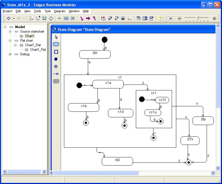
The statechart editor (displaying an example statechart to be transformed) is the following:
The transformation result for this example is the following:
References
1. Agrawal A., Karsai G, Shi F. Graph Transformations on Domain-Specific Models. Technical report, Institute for Software Integrated Systems, Vanderbilt University, ISIS-03-403, November 2003.
2. Harel D. Statecharts: a Visual Formalism for Complex Systems. Sci. Comput. Program. Vol 8, pp. 231-274, 1987.
3.