MOLA basics
A MOLA program, as any other model transformation program, transforms an instance of source metamodel into an instance of target metamodel. These metamodels are specified by means of UML class diagrams.
And similarly to many other transformation languages, the basic element of MOLA program is a rule, in turn consisting of a pattern and actions. The specifics of MOLA lie in the readable, but very expressive way how patterns are specified and in simple traditional control structures which determine the execution order of rules.
The very first and simple MOLA transformation program in this tutorial will be used to demonstrate the basics of MOLA patterns, rules and control structures organizing them.
Let us consider two natural ways how a simple directed graph can be coded.
The first way (A-coding) is a very basic one. A graph consists of Nodes and Edges, each Edge has exactly one start Node and one end Node.
The second way (B-coding) in addition to Nodes and Edges contains also connection points (of kinds Start and End). Any Edge here has a Start and End, and only these Starts and Ends are attached to Nodes (not the Edges themselves).
The task is to define a transformation in MOLA, which for a graph in A-coding would build a B-coding of the same graph.
At first these two ways of coding must be formalized in a metamodel – so that both kinds of coding would be models according to this metamodel. MOLA uses very simple means to define a metamodel – a UML class diagram consisting of classes, associations and generalizations. Classes can have attributes, which can have UML primitive types (String, Integer, Boolean) and Enumerations (which also can be defined in a metamodel) as their types. Associations have role names, multiplicities (and possible composition specification). Generalizations have their traditional meaning, but only single inheritance is supported. In general, it can be asserted that MOLA metamodel definition facilities are approximately those of OMG EMOF [?].
Typically a metamodel in MOLA consists of source part and target part (sometimes called a source metamodel and target metamodel). Fig1. shows the metamodel for the graph task, the source metamodel is on the left, its classes are light yellow.
|
|
Figure 1. Graph
metamodel
As expected, the source metamodel contains only two classes – ANode and AEdge, and two associations linking an edge to its start node and end node respectively.
The target metamodel (on the right, dark yellow) contains the basic classes BNode and BEdge, classes Start and End for the edge connectors and four associations linking these classes in a natural way. The metamodel is so simple that attributes are not used at all. The metamodel contains also one association, linking classes in source and target metamodels. This is a so-called mapping association, its role for the transformation process will be described later.
To illustrate how a source model actually A-codes a graph, an instance (object) diagram corresponding to the metamodel for a simple directed graph is shown in Fig.2.
This source model example (A-graph) will be used later to illustrate the transformation behavior.
|
|
|
Figure 2. Source
model example (A-graph)
It should be noted that node and edge names
are used just for visualization, it is not an attributed graph.
MOLA Pattern basics
The simplest MOLA pattern -
consists of one Class element - a class from metamodel and an
element name (a kind of "variable").
|
Here the class
is ANode (and name is a). A notation somewhat reminding UML object notation
is used for class elements. The pattern is contained in a rule (a grey
rounded rectangle). |
|
When the rule is executed on the model, this trivial pattern matches to all instances of ANode - a1, a2 and a3 (ai here is not the name attribute, but just some "internal" instance identifier).
In MOLA such indeterministic match situation is rarely used. A more realistic situation is that a loop (bold rectangle) is built on the basis of that rule, which iterates over all possible matches. One class element is marked to be the loop variable (bold) - namely all matches of it matter.
|
The loop is executed 3 times on the model
(and does nothing) - once for each match of an ANode instance |
|
More on rules and loops
A rule in MOLA (and other transformation languages too) typically not only does its pattern match, but also performs some actions - creates a class instance, creates a link, deletes an instance (or link), modifies attribute values of an instance (any combinations of these).
In MOLA a loop contains one main rule (which is called loop head and contains the loop variable) and possibly some other rules, which are also executed in each iteration (in this example there is only the loop head).
Whenever a rule matches (or a loop
head matches a current iteration), its actions are executed (using the
matched instances).
|
This rule (loop head) - extension of the
previous one - creates one class instance (of the class BNode) and one link
(corresponding to the association mappedA-mappedB) per iteration. |
|
Instance
creation in MOLA is shown by the same class element (of kind create - red dashed border), link creation - by link
line (also of kind create - red). The
correspondence of links to associations is shown by role names - at
least one of them.
When the loop is executed on the example
model, the following transformation occurrs (3 iterations are performed and 3
instances/links are created):
|
|
|
|
|
|
Figure 3.
Thus this loop builds a BNode for each ANode and links them by the mappedB link - the first step in the transformation of graph coding from A to B.
The association mappedB has been specially
introduced in the metamodel as so-called mapping association - its links
will be used by the next step of the transformation to find the relevant
instance of BNode when an ANode is selected.
A loop with more complicated pattern
Here again (see Fig.4.) the loop variable (aEd:AEdge) must iterate over all instances of the class AEdge, but the other part of the pattern - 4 class elements and 4 links must match too. Only such instances of AEdge are used for iteration, where all other elements match - there must be two instances of ANode linked by startNode and endNode respectively to the selected instance of AEdge and an instance of BNode for each of the ANodes. But it doesn't matter, whether one or more instances of e.g. strtN:ANode exist for the given instance of AEdge - it is a pure existence requirement.
|
|
Figure 4. More complicated pattern
But for this example it is easy to see that for each instance of AEdge just one relevant instance of strtN:ANode exists (linked by startNode), one instance of endN:ANode and so on - actually the other pattern elements are matched uniquely, when an AEdge is matched (for the example there are just 2 matches - over the result of the first loop).
This is a typical situation for MOLA -
patterns should be built so that the choice of the loop variable
determines other pattern elements uniquely - but it is not strictly required by the language semantics -
just a good practice.
The complete rule
|
|
Figure 5. Complete
rule
The actions in the loop (in fact, the loop head) build 3 instances and 4 links - thus a BEdge is built for each AEdge, also the corresponding connection (Start and End) instances and the relevant links.
In the example 2 BEdges are built, when
this loop is executed over the results of the first loop.
The complete MOLA program
|
|
Figure 6. Complete MOLA program
The only elements to be added to complete
the MOLA program, are Start node and End node (both as in UML
activity diagram) and control flows. In the simplest case one flow arrow
leaves each program element (loop), but rules may have also two exits
(branching, see later). The program is executed in the order the control flows
determine - the first loop (in its totality), then the second loop, which can
rely on the results of the first loop (created instances of BNode and mappedB
links).
The result of transformation execution
The following set of class instances and links is obtained when the complete transformation is applied to the example graph - the complete B-coding of the example graph has been obtained. The names of instances are for readability only - they actually are not part of the model.
|
|
Figure 7. Result
of transformation execution
Note that according to the specified
metamodel mapping links between A and B elements have been built only between
the corresponding nodes - this kind of links was used for correct building of
BEdges by the second loop.
Brief description of MOLA
A transformation in MOLA consists of
- metamodel (class model), currently one class diagram
- one or more MOLA procedures (diagrams), one of
which is the main
Facilities for describing the class model are those of standard UML class diagram, approximately at the EMOF level (classes, attributes, associations, enumerations). Packages may be used for making class names unique. Only single inheritance is permitted.
Currently the whole metamodel - both the source metamodel (defining the source models to be transformed) and the target metamodel (defining the resulting models) must be built as one common class diagram. There the mapping associations linking both parts of the metamodel can be (and typically are) added.
MOLA procedures define the executable part
of the transformation. The main executable unit within a procedure is the
already discussed rule, containing a pattern and actions. A
procedure is built from rules using constructs from traditional structural
programming - loops (including the already mentioned Foreach loop), branchings,
procedure calls - all in a graphical form, reminding UML activity diagrams.
MOLA procedure - an executable transformation unit - may contain some simple declarations - parameters and variables (primitive and class-typed) and the executable part.
The executable part is similar to UML activity diagram - it starts with a start node and contains:
|
|
loop symbols (Foreach and While) |
|
|
rules |
|
|
text statements |
|
|
procedure calls (including external ones) |
|
|
end nodes |
Start, loop and call symbols can have one outgoing control flow arrow. Rules and text statements can have one or two exits - the second one is labeled ELSE - this provides the traditional if-then-else construct. End nodes have no exits. Several control flows may enter one symbol - it means the ordinary merging of flows.
Loop body
(the interior part of the loop box) starts with a rule - loop head (which for
Foreach loops contains the loop variable), but may be followed (via control
flows) by all "independent" procedure elements - rules, (nested)
loops, text statements, calls. If a symbol within body has no exit, this means
that body actions for one iteration end here (end node is not used within loop
body).
More on patterns
In the simplest case considered so far, a pattern in a loop head or rule was just a connected subgraph of classes and associations (converted to class elements and links) from the metamodel. But in the general case a pattern may be more complicated. Its elements may contain attribute constraints - boolean expression on instance attributes, which must be true for an instance set to match the pattern. There may be NOT-elements - specifying that there must be no instance linked to the other part of pattern in the specified way and NOT-links - specifying that the given kind of link must not exist between these instances in order to match.
Another extensions are related to the
element match order - for some patterns it is required in the current MOLA
version to add annotations (or compiler pragmas) to pattern elements or
links. These annotations help MOLA compiler to find the correct order of
element match in a pattern. In future versions in most cases this information
will be deduced automatically from the metamodel. But sometimes annotations
will be useful as a manual optimization guide taking into account
"cardinality facts" not expressible in a UML class diagram. The next
examples need not such annotations.
Another example
The topic is Database design – building SQL table definitions from a Class model.
Several modifications of this true MDA-related task are shown. All they use a simplified UML Class model as the source model and a formalization of a fragment SQL database definition language as a target model.
The metamodels are the same for all
versions of the task, but the transformation task specifications are gradually
growing more complicated (and more realistic) and so are the transformations
in MOLA.
Metamodel
|
|
Figure 8. Metamodel
The domain part of the metamodel is the basic fragment (~EMOF) of the UML 2 Class model. Attributes (Properties in MM) here are assumed to have only Primitive types and Enumerations as their types, attributes are attached to the owning class via ownedAttribute association. An association end (also a Property in the MM), on the contrary, always has another Class as its type. Navigability of an association is specified by attaching the navigable end (Property) to the start class by the ownedAttribute association (otherwise the end belongs to its association via OwnedEnd, but the association link is present always). Both ends of an association are linked by the opposite link. The only extension of the metamodel is that a Class has isPersistent attribute.
The target part contains only the basic
notions of SQL – Table, Column and foreign key (FKey). Only simple foreign and
primary keys are used.
The first version of the task
In this version only the direct attributes and associations of a class are taken into account, inheritance is ignored. Only persistent classes are converted into tables, and each attribute corresponds to a column. For primary keys a special generated column is built, with a name derived from the table name.
Navigable
associations are transformed to foreign keys (the reference is in the direction
of navigability), for them also a special column is added to the owning table.
A foreign key references the table corresponding to the navigation target
class.
|
|
Figure 9. Main procedure
|
|
The first loop - a similar one to those in
the previous example - builds a table for each pesrsistent class. Two new
elements are present. The attribute constraint {isPersistent =
true}specifies that only those Class instances match the pattern where this
attribute has the given value. In general, any Boolean expression involving
class attributes may be used. The other is the assignment name:=@cl.name in the Table instance creation element - here also any expression
may be assigned to an attribute, there may be several assignments. The prefix
@cl shows that the name value from the matched Class is taken.
|
|
This loop again iterates over Classes -
those which a Table instance attached (in the previous loop). However, the loop
head only "organizes" the iteration, the proper job will be done by
other rules and nested loops, with flows showing the execution sequence
|
|
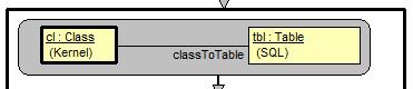
This is rule, but with a trivial pattern - the reference @tbl simply shows that the previously matched (in the loop head) instance is to be used (referenced) here. It is used to specify the end point of the new link and as a qualifier in assignment.
|
|
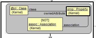
This is a loop head of a nested loop over instances of Property, linked by ownedAttribute to the same previously matched Class instance. In addition, these instances cannot have an association link to an Association instance - in other words, there is no Association instance in the model, which would be linked the specified way to the Property instance currently being matched. It is not hard to see, that namely such a pattern selects only properties which are attributes but not association ends (both are ownedAttributes for the current Class according to UML).
|
|
The subprocedure ProcessAttribute is invoked, using two previously matched instances prop and tbl as actual parameters (see later in this procedure that types are OK). This call is executed for each iteration of the nested loop.
|
|
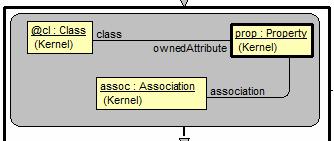
Another nested loop, this time over those instances of linked Property, which do have an association link to an Association instance (from the metamodel it follows that there is no more than one such). This way only navigable association ends are iterated over - but not attributes. It should be noted that frequently a nested loop is based on a "many-link" from an instance selected above (and appearing as a reference - here @cl).
|
|
Another subprocedure call - for processing
the given association
|
|
One more subprocedure call. Should be the
final one, because other column types are referenced (see details later)
Subprocedures
ProcessAttribute
This is the first of the subprocedures (Fig.10). It builds a column for an attribute (Property) and adds this column to the given Table. Note the two parameter symbols - with type Property and Table respectively. These are in-parameters (there are also inout ones). The ordering is shown by explicit numbers. Parameter type match is as for OOP languages - the actual parameter must be of the given type or a subtype of it.
Other new element is a rule with nontrivial pattern and two exits. The first such rule checks whether the passed Property instance has a PrimitiveType. If it is so (the pattern matches), the non-marked exit is taken and corresponding "building rule" (which has no proper pattern) is executed. The reference to @pt may be used here, since we know that the previous rule has matched. If the type of the Property is not primitive, the ELSE exit is taken (and no match actually has occurred).
The other non-trivial rule acts in a
similar way. Its ELSE-exit leads to an external procedure call - we assume that
there is an external procedure (not in MOLA, but in some OOP language, e.g.,
C++) ShowMsg, which can display its String parameter value in a Windows message
box. This procedure has to be compiled together with MOLA (which also finally
produces some C++ code). There are no proper I/O statements in MOLA, therefore
such a workaround is required for building user dialogs.
|
|
Figure 10. ProcessAttribute procedure
ProcessAssociation and CompleteForeignKeys
These two subprocedures has no new MOLA elements.
The first one - ProcessAssociation uses a rule with pattern (containing an attribute constraint {isPersistent = true}). If the rule does not match (the selected Class instance - there is always exactly one such - is not persistent), the procedure instantly exits - there is no ELSE exit for the rule. But such a reaction is appropriate, since non-persistent classes are ignored in table building. It should be noted, that this procedure is invoked inside the main table element building loop - for the the other association end (which may appear later on during the iteration) nothing more than its table is required (all tables were built in the very first loop).
The other procedure is an independent "postprocessor" loop over all FKey instances, it has no parameters. It is built as a "postprocessor" (after the main loop has completed), since it uses a type (of the PK column) from the table at the other association end (which could be unknown if this action were performed "inline" the main loop). It should be noted that in this simple setting the required type actually is a known constant, but the given solution is presented as a frequently used "design pattern" in MOLA. Note also the non-trivial pattern in the loop head, which nevertheless actually matches for all instances of FKey - its role is to locate the relevant environment, for use in the next building rule.
This completes the example description.
|
|
|
Figure
11. ProcessAssociation and
CompleteForeignKeys procedures
The second version of the task
In this version the inheritance is also taken into account, both for attributes and associations of a class. Inherited elements are processed the same way as the direct ones. Only single inheritance is assumed for this example.
Otherwise the transformation is specified
the same way as in the previous example. Therefore the solution is also quite
similar, except for inheritance processing, which is done using recursive
procedures - a natural solution for "transitive closure" type of
tasks.
|
|
Figure 12. Metamodel
Formally the same metamodel could be
reused since the generalization was already present. But this version requires
two temporary associations - associations which are not present in the
source model and are not required in the result. They are used only by some
transformation procedures - in this case, recursive ones. The temporary
associations (inheritedAttribute and inheritedAssoc) are in green
color. The first association is assumed to hold all inherited attributes, the
other one - association ends. The use of temporary associations (and temporary
attributes for existing classes) is typical for more complicated
transformations in MOLA (and other transformation languages too).
Transformation - main
The general
solution schema is the same as for the previous version of the task. Initial
part of the main procedure is literally the same.
|
|
Figure
13. Main procedure
|
|
The difference starts here where two
recursive subprocedures are invoked for processing inheritance. The procedure
ResolveInheritedAttributes builds all inherited attributes of the given class -
builds all links of kind inheritedAttribute for this class (since the procedure is
recursive, it may build these links also for some other classes too, but it is
not used). Similarly, the procedure ResolveInheritedAssociations builds all
inherited navigable association ends from a class (as inheritedAssoc links)
|
|
Attribute processing is similar to the
previous case, but based on the temporary association inheritedAttribute found in the
previous step. The pattern is simpler, since no more mix of attributes and
navigable association ends appears when forming the loop for properties.
|
|
Association
processing is also similar, based on inheritedAssoc association.
|
|
Final part also similar, but a new procedure is added for "cleaning up" the model - in case of another transformation would be applied to the model.
Recursive subprocedure for inherited attributes
|
|
Figure 14. ResolveInheritedAttributes
|
|
Delete links of this kind if they were set by previous invocations
|
|
A typical use of recursion for finding a
transitive closure of a relation. If there is a superclass for the given class,
do the same for the superclass first.
|
|
After the return from the recursive call,
use the results of this call. Here, at least the direct atributes of the
superclass would be linked by inheritedAtribute, but more links could be built,
if the inheritance stack is higher.
|
|
Finally, perform the recursion basis -
relink the direct attributes of the class via inheritedAtribute. Attributes are
separated from association ends as before.
It is easy to see that for classes high in
the inheritance hierachy the given procedure actually will be invoked many
times during the execution of main loop. Here it could be avoided by adding a
temporary attribute (e.g., isOK) for Class in MM. But for a "changing
environment" only this way is usable - temporary associations need to be
refreshed upon usage.
Subprocedure for inherited associations
A remark not related to this example -
currently in MOLA if you delete the link "used" for locating the loop
variable (here inheritedAssoc) the loop variable instance is no more accessible for another usage
in this iteration - it must be stored in another variable if it is to be
used after delete.
|
|
Figure 15. ResolveInheritedAssociations Procedure
This recursive subprocedure is very
similar to the previous one, therefore no more comments are necessary
Other subprocedures
ProcessAttribute – identical to the
first version
ProcessAssociation – identical to the
first version
CompleteForeignKeys – identical to the
first version
DeleteInheritanceInfo – the
double loop deletes any temporary link to a Property for any Class in the model
|
|
Figure 16. DeleteInheritanceInfo procedure
This completes the second version of the
example
Example summary
The three provided examples have illustrated the use and role of nearly all MOLA constructs (except Text statements and use of variables). Also not all possible syntax elements of expressions in MOLA (for constraints and assignments) have been demostrated, only the mostly used ones.
However, these uncovered features are quite unspecific to MOLA - they closely remind those in traditional programming languages. The full syntax of MOLA can be found in the reference manual.
Also, the main "design patterns" in MOLA have been demonstrated - existential sematics of patterns, use of nested loops for processing structured elements, use of rules for branching, use of NOT-elements as negative constraints, use of temporary associations, recursive procedures for finding transitive closure, role of loop "postprocessors". Certainly, there are more of them, but these seem to be the most used ones.
Another example
This example is from the area of tool building. UL IMCS has started a new project – Metamodel and Transformation based Tool Framework (TTF). According to this framework a diagram presentation metamodel is designed and an engine (Eclipse based) is built which can visualize a correct presentation model (an instance set corresponding to this metamodel) – display a visible diagram containing the given elements. In addition, this engine can intercept tool user actions upon this diagram (such as a request to create new diagram element, edit data visible in a diagram element, move a diagram element etc.). Pure "graphical" actions such as move are performed by the engine directly, but all "logical" actions are converted into commands – special instances (or linked instance groups) which then are performed by appropriate transformations. Thus a specific modeling tool functionality is determined by the standard engine and the supplied set of transformations. These transformations actually determine the complete logic of the tool – what elements can be created and where, how the modification of data is reflected into visible diagram elements, what are correct data and so on.
In particular, these transformations have to maintain the mapping between a domain metamodel (such as whole or part of UML metamodel) and the fixed presentation metamodel for this framework. The mapping determines what kind of diagram element (node, part of node etc) corresponds to the given domain element.
The complete presentation metamodel for TTF is quite complicated, but the Fig.1 shows the most essential part of it – proper diagram element structure. There is the Diagram, which consists of Diagram Elements – Nodes and Edges. Node is still an abstract superclass with its most important subclass being the CompositeNode – an element such as class node, enumeration node in class diagram, action in activity diagram and so on. A CompositeNode can contain Labels – text elements (such as class name, class stereotype, one attribute line, enumeration name in class diagram). In addition, a CompositeNode can contain a Compartment – a related group of Labels – such as the complete set of attributes for a class.
When a domain model element (class, enumeration,…) has been modified by the tool user via Property dialogs (another part of presentation metamodel and engine, not shown here), transformations have to update the relevant diagram elements – those to which the mapping links from the modified element go. This may be one element in one diagram or several elements in several diagrams – as determined by links. In addition, all updates to these diagram elements must be notified to the presentation engine – links must be set to a singleton (i.e., a class which always has exactly one instance) class Changes. Some of the domain elements must be visualized also in the project tree (determined by another part of the presentation metamodel and another kind of mapping links) as DomainElementNodes. If an element is (or remains) selected, its attributes appear in the appropriate fields of property dialog, including the Properties title.
In the example the domain metamodel is the most essential fragment of UML 2 Class model (approximately equivalent to OMG EMOF metamodel). The example presents a solution to the following task for Enumeration instances. After the user has modified an Enumeration name (via Property dialogs, outside the scope of the example), at first it is necessary to check whether the new name is valid – it must be unique within the containing package (which can also be the whole model). Then the enumeration name is updated in the domain instance. The Enumeration instance may be visualized in one or more Class diagrams, in all these places (i.e., the corresponding CompositeNodes) the name Label must be updated. In addition, the enumeration may be used as a type for some attributes (Property instances), the Label corresponding to such an attribute in a class CompositeNode (one or more) must also be updated accordingly. Finally, the relevant DomainElementNode in the project tree and the Properties title must also be updated. All modified presentation instances must be linked to Changes. One more general comment to the task is that a DiagramElement is found to be of an appropriate kind via its diagElementKind_ attribute.
The main MOLA procedure
for this task is upd_ModifyEnumName (Fig.2).
|
|
Figure 1. Metamodel
|
|
Figure 2. upd_ModifyEnumName
procedure
upd_ModifyEnumName procedure receives as parameters from the general command manager procedure the reference to the Enumeration instance to be processed (@en) and the new name (@newname, a parameter in MOLA may also be of a primitive type). The procedure uses two primitive-typed variables – @isOK and @qualPref. The @isOK variable is initialized to true value via a textual assignment, then utl_NameUniquePackgElem is invoked (its third parameter is of in-out kind, currently there are no proper functions in MOLA). The invocation results are analyzed in a textual constraint, in case of uniqueness violation a message to user is shown by means of an external procedure invocation. If the check is OK, a simple rule updates the domain instance. Then a loop is started over all CompositeNodes which visualize the given Enumeration (i.e., are linked to it by the mapping link present). In all these nodes the EnumNameLabel must be updated accordingly.
The invocation of upd_UpdateEnumReferences updates all attribute labels, where the attribute is typed to this enumeration. The last rule updates the corresponding project tree node (mapped via treePres) and the title of Properties (the enumeration is still reflected in Properties), but utl_QualifiedNamePref must be invoked to display the full qualified name in the title.
The procedure utl_NameUniquePackgElem (Fig. 3) is quite straightforward, note only the use of MOLA "existential semantics" for the sole rule – we must find at least one instance of PackagableElement with "another identity" (self<>@el), but with the same name. If the pattern matches, there is at least one such element – it doesn't matter, whether there is more. Note also the setting of the in-out parameter by a simple textual assignment.
|
|
Figure 3. utl_NameUniquePackgElem
procedure
The procedure upd_UpdateEnumReferences (Fig. 4) in a double loop updates all AttributeLabel Labels, which visualize a Property, having this Enumeration as its type.
Finally, the procedure utl_QualifiedNamePref (Fig.5) emulates a while-loop by simple gotos, in order to concatenate all Package names, into which the given Enumeration is included.
|
|
Figure 4. upd_UpdateEnumReferences procedure
|
|
Figure 5. utl_QualifiedNamePref procedure